(technical specification v11.03)
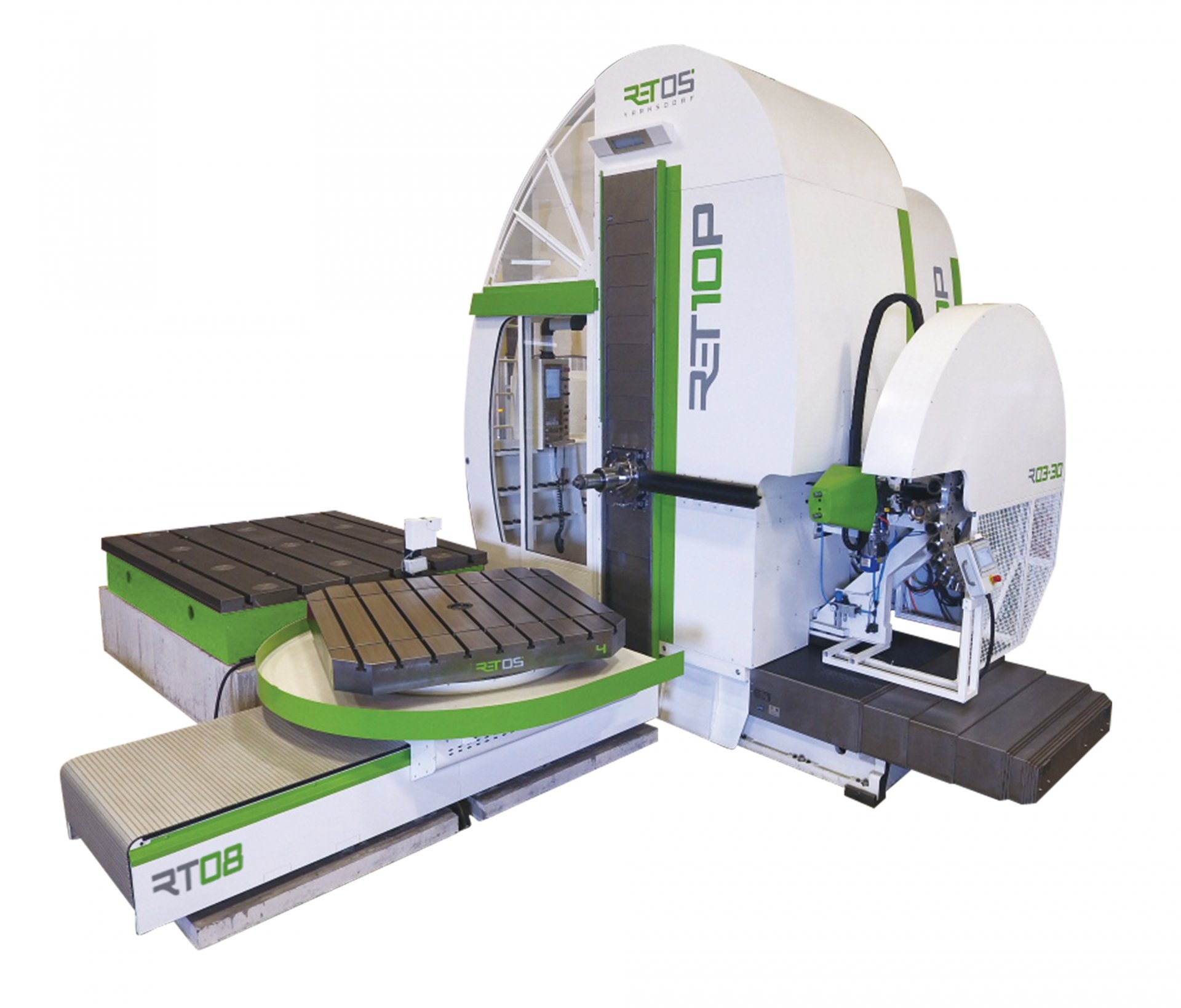
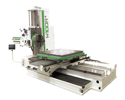
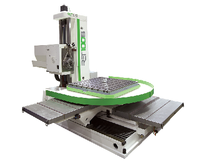
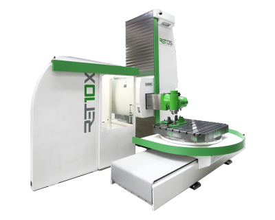
The RET10P is a contouring floor type of a horizontal boring machine designed by RETOS VARNSDORF s.r.o. It fully meets the requirements on high production productivity, with maximum consideration of safety and operation convenience, as well as thoughtfulness towards the environment.
Features
- contouring floor type of horizontal boring machine
- transversal travelling column
- 3/4 linear axes
- sliding ram / workspindle or a combination of them
- machine suitable for machining of large workpieces
- suitable for roughing as well as for finishing
- travel ranges, number of axes, and clamping surfaces and the level of coverage can be customized according to your specific needs
- workpiece is clamped to a clamping plate or a rotary table (it is not a part of the machine)
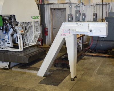
- according to your needs, option of fitting with a broad spectrum of accessories, such as automatic tool changing systems (ATC), various milling heads and milling head changing systems (AHC), a facing head, tool cooling kit (CHZ), cooling through spindle axis (CHOV), oil-mist cooling (CHM) or swarf conveyor
- ready for "Industry 4.0"
Controlling of the Machine
- all functions of the machine, except for clamping and unclamping, are controlled via the control panel, which consists of a keyboard, a switch panel and an LCD monitor
- the clamping and unclampig of tools is controlled by the key on the wall inside the operator platform
- the control panel is supplemented by a portable control panel (handwheel), which duplicates some of the basic functions of the machine control
- the control panel is situated on the operator platform, which is an integral part od the group column/headstock
- the control system allows manual, semiautomatic and fully automatic modes
- the standard operator’s site is on the operator platform
- an alternate operator’s site is outside the operator platform and is usable only in the fully automatic mode
- the standard communication interface allows a connection with the Ethernet for easy administration and distribution of technological programs, machine operation monitoring, diagnostics or servicing of the control system, etc.
Machine design can be customized.
Standard Version
Control System
- HEIDENHAIN TNC 640 + handwheel
- HEIDENHAIN drives
- SIEMENS motors
Powered Axes
- X – transversal travel of column slide on bed
- Y – vertical headstock travel on column
- Z – ram travel
- S – workspindle rotation
Machine Capabilities
- X, Y, Z axes powered in interpolation
- linear interpolation
- circular interpolation
- spiral interpolation
- spacial interpolation – spline in space
- interpolation of S and Z axes – spindle turning depending on the Z axis position – enables thread cutting without using a compensating bushing
- potential limitations regarding the machine capabilities due to territorial differences in the control system’s NC program
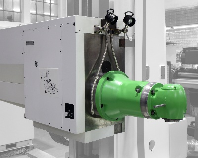
V1 Headstock
- sliding ram
- non-sliding workspindle
- spindle cavity blown with air during tool-changing cycle
- spindle driven by two speed ranges – speed reduction gear
- hydraulic shifting of each speed range
- set-up for tool cooling kit on ram front side
Kinematics of the X Axis
- 2 brushless digital servomotors with servo-drives (master/slave)
- 2 planetary gearboxes with minimum clearance
- rack inserted into the bed
Kinematics of the Y Axis
- ball screw
- clearance-free gearing by timing belt
- brushless digital servomotor with servo-drive
Kinematics of the Z Axis
- brushless digital servomotor with servo-drive
- planetary gearbox with minimum clearance
- ball screw
Group Guidance
- X, Y, Z axes – Caged Roller LM Guides
Lubrication
- central, axial lubrication
- frequency of lubrication cycles correlates with travelled track of the particular group
Clamping
- X, Y, Z axes – not clamped – positional feedback
Hydraulic Power Packs
- HYTOS lubrication set – lubrication of all axes
- HYTOS pressure set – unclamping of the tool
Position Measurement
- X, Y axes – HEIDENHAIN absolute digital optical linear encoders
- Z axis – absolute rotary encoder in motor
- S axis – HEIDENHAIN incremental rotary encoder
Energy Distribution
- IGUS chain energy carriers
Coverage of Machine
- X axis – bed guideways protected by telescopic way cover
- Y axis – complete coverage of the group column/headstock
Optionally + Peripheries
CE – compulsory in EU
- comprehensive safety elements according to the applicable legislation and technical standards
- covered operator platform
- working area of the machine is fenced off
- further elements arising from the risk analysis
Control System
- SIEMENS ONE + handwheel
- SIEMENS drives and motors
V2 Headstock
- sliding ram – Z axis
- sliding workspindle – W axis
- W drive – servomotor, planetary gearbox, ball screw
- W guidance – Caged Roller LM Guides
- W clamping – not clamped – positional feedback
- W admeasurement – absolute rotary encoder in motor
- for further details see V1 Headstock
V3 Headstock
- non-sliding, fixed ram
- sliding workspindle – W axis
- W drive – servomotor, planetary gearbox, ball screw
- W guidance – Caged Roller LM Guides
- W clamping – not clamped – positional feedback
- W admeasurement – absolute rotary encoder in motor
- for further details see V1 Headstock
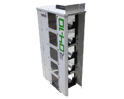
ATC R04-10 – Automatic Tool Changer
- rack system on the clamping plate
- application of more racks on different places possible
- for the manipulation with tools the machine workspindle is used
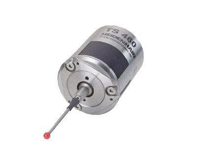
- including TS460 workpiece touch probe
| ATC R04-10 Parameters |
|
|
| Tool changing time |
20 |
s |
| Number of tools in one rack |
10 |
pcs |
| Maximum number of racks |
6 |
pcs |
| Tool pocket pitch |
130 |
mm |
| Maximum tool diameter |
125 |
mm |
| Maximum tool length |
500 |
mm |
| Maximum tool weight |
15 |
kg |
| Weight without tools |
110 |
kg |
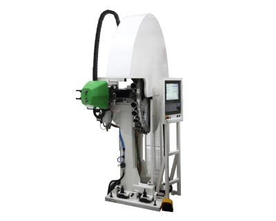
ATC R03-30 – Automatic Tool Changer
- system mounted on the machine column
- magazine with servodrive for tool pocket positioning
- changer driven electrically / pneumatically
| ATC Parameters |
R03-30 |
|
| Tool changing time |
15 |
s |
| Number of tools |
30 |
pcs |
| Tool pocket pitch |
130 |
mm |
| Maximum tool diameter – unrestricted |
125 |
mm |
| Maximum tool diameter – with free pockets |
200 |
mm |
| Maximum tool length |
500 |
mm |
| Maximum tool weight |
15 |
kg |
| Maximum weight of tools in magazine – total |
250 |
kg |
| Maximum tool unbalance in magazine-wheel |
50 |
kg |
| Maximum wheel speed |
8 |
rpm |
| Operating air pressure |
5 |
bar |
| Required air purity |
40 |
microns |
| Weight without tools |
1240 |
kg |
CHZ – Tool Cooling Kit – Fluid
- tool cooling set with jets on headstock front side
- cooling unit integrated into the foundation of the machine
- unit with pump and level gauge
- tank (pit) volume approx. 1000 l (usable)
- maximum pressure 4 bar / 32 l/min
- setup for tool cooling always included – distribution pipes, jets
CHZ-V – Tool Cooling – Air
- cold air gun
- cooling without a thermal shock
- positive impact on the accuracy and the surface quality
- high reliability
- environmentally friendly
- almost zero operating costs
CHOV-K – Cooling Through Spindle Axis – Fluid
- not possible to add into configuration, once the production has started
- separate cooling unit with filter and magnetic swarf separator
- tank volume 1000 l
- maximum pressure 40 bar / 30 l/min
- other alterations to machine and CE features
- for pressure higher than 10 bar a workpiece or machine cover is necessary
CHOV-V – Cooling Through Spindle Axis – Air
- not possible to add into configuration, once the production has started
- maximum pressure 5 bar
CHOV-M – Cooling Through Spindle Axis – Oil-Mist
- not possible to add into configuration, once the production has started
- separate programmable cooling unit
- maximum pressure 5 bar
CHM – Oil-Mist Cooling
- can be added to machine at any time
- easy to install
- easy to use
Swarf Conveyor
- placed in the foundation of the machine (along the bed)
Clamping Plate
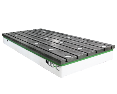
- UD4C clamping plate – 4020 x 1885
- UD4D clamping plate – 2420 x 1885
| UD4C Clamping Plate Parameters |
| Clamping plate surface |
4020 x 1875 |
mm x mm |
| Width of T-slots |
36 H12 |
mm |
| Clamping plate loading capacity |
80000 |
kg |
| Clamping plate weight |
8200 |
kg |
| Basic dimensions – length x width x height |
4020 x 1885 x 400 |
mm |
| UD4D Clamping Plate Parameters |
| Clamping plate surface |
2420 x 1875 |
mm x mm |
| Width of T-slots |
36 H12 |
mm |
| Clamping plate loading capacity |
45000 |
kg |
| Clamping plate weight |
5000 |
kg |
| Basic dimensions – length x width x height |
2420 x 1885 x 400 |
mm |
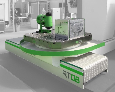
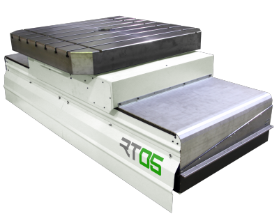
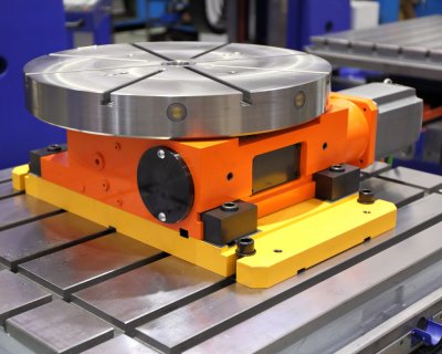
RT05, RT08 Rotary Table
- V1 – positioning rotary table (RT08)
- V2 – interpolation rotary table (RT05 and RT08)
- as option or complement of the clamping plate
- complements the machine travels by V and B axes
- controling is fully integrated into the control system of the machine
- enlarges the operational capabilities of the machine
- B axis powered only positionally (V1)
- X, Y, Z, W, V, B axes powered in interpolation (V2)
- cylindrical interpolation by using the rotary table (V2)
| RT05 Table Parameters |
| Table loading capacity – rotation |
5000 |
kg |
| Table loading capacity – static |
8000 |
kg |
| Table clamping surface |
1250 x 1250 |
mm x mm |
| |
1500 x 1500 |
mm x mm |
| Width of T-slots |
22 H8 |
mm |
| V…longitudinal travel of table |
1000 / 1500 |
mm |
| Feeds…V – manual mode |
4 - 500 |
mm / min |
| Feeds…V – automatic mode |
4 - 10000 |
mm / min |
| Rapid traverse...V |
20000 |
mm / min |
| Feeds of table rotation…B |
0 - 5 |
rpm |
| Rapid traverse of table rotation…B |
10 |
rpm |
| Table weight |
4000 - 5500 |
kg |
| Basic dimensions – length |
2600 / 3200 |
mm |
| Basic dimensions – width |
1250 / 1500 |
mm |
| Basic dimensions – height |
850 |
mm |
| RT08 Table Parameters - V1, V2 |
| Table loading capacity |
8000 |
kg |
| Table clamping surface |
1250 x 1250 |
mm x mm |
| |
1500 x 1500 |
mm x mm |
| |
diameter 1300 |
mm |
| Width of T-slots |
22 H8 |
mm |
| V…longitudinal travel of table |
1000, 1250, 1500, 1750, 2000 |
mm |
| Feeds…V – manual mode |
4 - 500 |
mm / min |
| Feeds…V – automatic mode |
4 - 10000 |
mm / min |
| Rapid traverse...V |
25000 |
mm / min |
| Feeds of table rotation…B...V1/V2 |
0–8 / 0–16 |
rpm |
| Rapid traverse of table rotation…B...V1, V2 |
14/21 |
rpm |
| Table weight |
3600 - 4200 |
kg |
| Basic dimensions – length |
2670, 2920, 3170, 3420, 3670 |
mm |
| Basic dimensions – width |
1800/2106 |
mm |
| Basic dimensions – height |
900 |
mm |
Accessories
Standardly Delivered Accessories
- VP10–170 spindle guiding support – for sliding spindle only
- VK-ISO50 cleaning brush
- clamping adapters - 15 pieces
- KM anchoring kit
- basic tool kit for operation and maintenance of the machine
- basic spares kit
- technical documentation
Optional Accessories
- VP10–320 spindle guiding support – for sliding spindle only
- VP10–470 spindle guiding support – for sliding spindle only
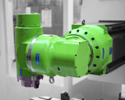
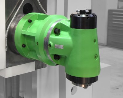
- HPR50, FP40 vertical manual milling heads
- HUR50, UFP40 universal manual milling heads
- SEMPUCO vertical and universal indexing head
- SEMPUCO universal NC milling head
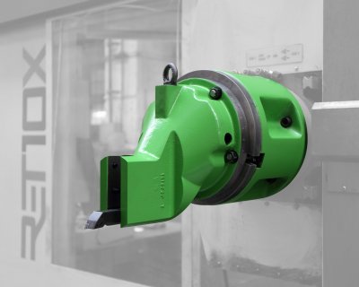
- COGSDILL facing head – with V2, V3 headstocks only (spindle feed necessary)
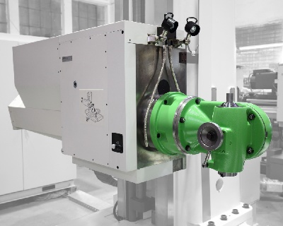
- SHC – semiautomatic head changer
- AHC – automatic head changer
- MT03/MT03X rotary table
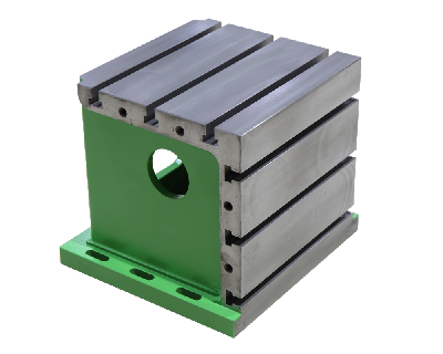
- UK500, UK1000, UK2000, UK2500, UK3000 clamping cube
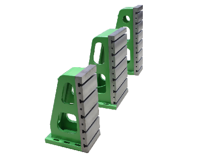
- UU800, UU950, UU1120, UU1450, UU1620, UU2000, UU2500, UU3000 clamping angle plates
- spares kit for 3-year operation
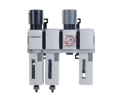
- HEIDENHAIN DA400 compressed-air filter system
- 3D touch probes with radio/infrared signal transmission (Heidenhain/Renishaw/Hexagon)
- HEIDENHAIN HR550 FS wireless handwheel
- CE security mode 3 (for German market only)

